 Matlab
 Simulink
 NS3
NS3 OMNET++
 COOJA
COOJA CONTIKI OS
 NS2
NS2
Solar Tracking System Simulation efficiently monitors the position of the sun and preserves the module at an optimal angle for best energy output. For optimal simulation results you can rely on our developers get high grade by accessing our services for more updates read the ideas that we have listed by us. In the motive of assisting, you in developing and simulating a solar tracking system with the application of MATLAB/Simulink, we provide a detailed procedural instruction:
- Introduction to Solar Tracking Systems
To follow the sun’s direction, a solar tracking system guides the solar panels to enhance the energy absorption. This system involves three significant components, they are:
- Sensors: The location of the sun is identified through this sensor.
- Controller: It efficiently operates the sensor data and alters the direct of solar panels.
- Actuators: Solar panels are moved by this actuator.
- Elements of the Simulation
- Solar Panel Model
- Power outputs of solar panels are signified in this model.
- It is highly reliant on incident angle of sunlight.
- Sun Position Estimation
- Over the sky, it simulates the direction of the sun.
- For maximum sun radiation, this estimation specifies the best angle.
- Control System
- The control system involves actuators, a controller like PID and sensors.
- In accordance with the estimated best angle, it modifies the panels.
- Tracking Mechanism
- On the basis of control system results, tracking techniques direct the solar panels in an effective manner.
- It simulates physical activities and limitations.
- Configure the Simulation in MATLAB Simulink
- Open MATLAB and Simulink
- Install MATLAB :
Initially, download the MATLAB. To open the Simulink platform, type Simulink in the command window of MATLAB.
- Design a New Model
For creating a novel model, click “Blank Model”.
- Develop the Solar Panel Subsystem
- Generate a Subsystem:
- From the Simulink library under Ports & Subsystems, include a Subsystem block.
- We have to double-click and specify the internal elements.
- Incorporate Elements Inside the Subsystem:
- Constant Block: Panel area and its capability is signified here.
- Gain Block: For power output, it indicates the transmission factor.
- Product Block: To compute power output, it multiplies input irradiance with efficiency and area.
- Connect the Elements:
- Depending on the sunlight angle, simulate the power output by connecting Constant, Gain and Product blocks.
- Sun Position and Irradiance Calculation
- Include a Sine Wave Block:
- Over the sky, it depicts the activities of the sun.
- Outside of the subsystem, include the block and connect it with the system input.
- Specify the Sine Wave Parameters:
- In order to indicate the maximum solar radiation, determine the amplitude.
- Simulate the routine solar cycle by modifying its frequency.
3.4 Develop the Control System
- Encompass a PID Controller:
- We have to drag a PID Controller block into the model from the Simulink Library (under consistent).
- From the estimation of sun location, acquire the result by connecting the PID controller.
- Set up the PID Controller:
- To adjust the system response, construct the proportional, derivative and integral gains.
- Include a Sensor System:
- Simulate sensor input and output with the aid of Gain blocks.
- On the basis of the panel’s existing direction, we should connect a sensor which offers significant reviews.
3.5 Model the Tracking Mechanism
- Incorporate a DC Motor Block:
- From the Simscape Electrical library, acquire the benefit of DC Motor block.
- To simulate the activities, we must connect the motor to the PID controller.
- Set up the Motor:
- Coordinate with solar tracking actuators by configuring the motor parameters like mechanical features, inductance and resistance.
- Include a Rotational Motion Sensor:
- Evaluate the direction of panels by implementing the Rotational Motion Sensor block.
- To offer reviews for the control system, connect the sensors.
3.6. Simulation Configuration
- Incorporate a Scope Block:
- Visualize the result by inserting a Scope block from the Simulink Library (under Sinks).
- With the findings of the solar panel model and the motor, connect the scope.
- Develop Simulation Parameters:
- To create simulation parameters, Simulation > Model Configuration Parameters.
- The step size, start and stop times, and solver type should be specified.
- Executing and Evaluating the Simulation
- Connect Components and Execute the Simulation
- Connect Overall Components:
- Verify the entire blocks, whether it is correctly connected with control signals and flow of data.
- Among the sun position estimation, tracking mechanisms and controller, recheck the connections.
- Execute the Simulation:
- To begin the simulation, click the Run button.
- As concentrating on panel direction and power output, the system activities of the scope should be analyzed.
- Evaluate the Findings
- Analyze Scope Outputs:
- To observe the system, to what degree it monitors the sun, examine the power output.
- For verifying, whether it follows the correct path, evaluate the activities of solar panels.
- Adjust Parameters:
- Enhance the flexibility and response time by modifying the PID controller.
- In order to coordinate with real-world scenarios, the sun position model has to be altered.
- Re-execute Simulation:
- To examine modifications and ensure developments, create potential alterations and execute the simulation.
Example MATLAB Code for Solar Tracking Simulation
For the Simulink model, the instance of configuring a simple solar tracking system with the application of MATLAB is provided here:
% Define solar panel parameters
panel_area = 1.6; % in square meters
panel_efficiency = 0.15; % 15%
% define sun position as a sine wave (simplified model)
Amplitude = 1000; % max solar irradiance in W/m^2
Frequency = 2 * pi / 86400; % one cycle per day
% PID controller parameters
KP = 1.2;
Ki = 0.5;
KD = 0.1;
% create Simulink model
Open system (new_system (‘SolarTracking’));
% add blocks for solar panel model
add_block(‘built-in/Constant’, ‘SolarTracking/Panel_Area’, ‘Value’, ‘1.6’, ‘Position’, [100, 100, 130, 130]);
add_block(‘built-in/Gain’, ‘SolarTracking/Panel_Efficiency’, ‘Gain’, ‘0.15’, ‘Position’, [150, 100, 180, 130]);
add_block (‘built-in/Product’, ‘SolarTracking/Power_Output’, ‘Position’, [200, 100, 230, 130]);
% connect blocks
add_line (‘SolarTracking’, ‘Panel_Area/1’, ‘Panel_Efficiency/1’);
add_line (‘SolarTracking’, ‘Panel_Efficiency/1’, ‘Power_Output/1’);
% add sun position (sine wave)
add_block (‘simulink/Sources/Sine Wave’, ‘SolarTracking/Sun_Position’, ‘Amplitude’, ‘1000’, ‘Frequency’, ‘2*pi/86400’, ‘Position’, [50, 50, 80, 80]);
add_line (‘SolarTracking’, ‘Sun_Position/1’, ‘Power_Output/2’);
% add PID controller for tracking mechanism
add_block(‘simulink/Continuous/PID Controller’, ‘SolarTracking/PID_Controller’, ‘P’, ‘1.2’, ‘I’, ‘0.5’, ‘D’, ‘0.1’, ‘Position’, [300, 100, 350, 130]);
add_line (‘SolarTracking’, ‘Power_Output/1’, ‘PID_Controller/1’);
% add DC Motor block
add_block (‘simscape/Power Electronics/DC Motor’, ‘SolarTracking/DC_Motor’, ‘Position’, [400, 100, 450, 130]);
add_line (‘SolarTracking’, ‘PID_Controller/1’, ‘DC_Motor/1’);
% add Scope block to visualize output
add_block (‘simulink/Sinks/Scope’, ‘SolarTracking/Scope’, ‘Position’, [500, 100, 550, 130]);
add_line (‘SolarTracking’, ‘DC_Motor/1’, ‘Scope/1’);
% Run the simulation
Sim (‘SolarTracking’, 86400); % Simulate for one day
How to simulate a solar tracking system using MATLAB Simulink?
To simulate a solar tracking system with the application of MATLAB/Simulink, you must follow the extensive and structured format. For assisting you in this process, a clear format with step-by-step procedure is offered by us:
Step 1: Set Up Your Simulink Environment
- Open MATLAB :
Initially, install the MATLAB. In the MATLAB command window, type simulink to open Simulink.
- Design a Novel Model:
On the starting page of Simulink, click “Blank Model” to develop a new model.
Step 2: Specify the Solar Tracking System Components
The following components are commonly involved in a solar tracking system,
- A solar panel model.
- To identify the angle of sunlight, it includes a sensor system.
- For computing the required modifications and operating sensor data, a controller is involved.
- It incorporates a tracking mechanism to shift the solar panels.
Step 3: Design the Solar Panel
- Include Solar Panel Block: In order to determine the solar panel and its features, make use of Subsystem block.
- Initially, open the Simulink Library Browser and direct to Subsystems & Models.
- On our model, drag a Subsystem block.
- To specify the internal system of your panel, we have to double-click on the subsystem.
- Determine the Solar Panel Output:
- In terms of incident sunlight, design the solar panel’s power by including Gain and Function blocks in the subsystem.
- For determining the position and capability, apply a basic formula P=G* A* η (Power = Solar Irradiance * Area * Efficiency) on where we modify the gain blocks.
Step 4: Incorporate Sensors to Identify Sunlight Angle
- Develop Sensor Blocks:
- Eventually, simulate the divergence of sunlight with the application of Sine Wave blocks.
- To indicate the frequent and seasonal modifications in sunlight angle, the amplitude and frequency required to be altered.
- Estimate the Sun Angle:
- In accordance with solar panels, design the angle of the sun by using lookup tables or trigonometric functions.
Step 5: Model the Controller
- Insert a PID Controller:
- Direct to Continuous in the Simulink Library Browser. On our model, drag a PID controller.
- As a means to handle the tracking mechanisms, set up the PID parameters.
- Execute Control Logic:
- Regarding the optimal angle which is acquired from the sensor data, contrast the existing angle of the solar panel by developing logic.
- The required modification signals need to be exhibited to the tracking mechanism.
Step 6: Develop the Tracking Mechanism
- Include Actuator Blocks:
- For indicating the actuators which shift to the solar panel, acquire the benefit of Rotational Electromechanical Converter or DC Motor.
- To the output of the PID controller, connect these blocks in an efficient manner.
- Simulate the Panel Activities:
- In terms of control signals, upgrade the direction of panels by connecting the motor output with a block.
Step 7: Generate the Simulation Platform
- Incorporate a Time Scope:
- Periodically, visualize the modifications of angle and output power of the solar panel through including a Scope block from the Simulink Library.
- Set up Simulation Parameters:
- Choose Simulation > Model Configuration Parameters to develop the simulation parameters.
- For our simulation, specify the step size, solver type and start and stop times.
Step 8: Link Components and Execute the Simulation
- Link Entire Blocks:
- Crucially, we should verify the blocks (Actuators, Solar panels, Sensors and Controller) whether they are connected appropriately.
- To examine the data transmission, if it is flow properly through the system, the inputs and outputs have to be rechecked.
- Execute the Simulation:
- Begin the simulation by clicking on the Run button.
- For analyzing the solar panels on how it adapts with high power output, the output needs to be evaluated on the scope.
Step 9: Assess and Enhance
- Analyze the Findings:
- Represent the capability of our solar tracking system by assessing the results of scope.
- We have to seek for any areas or gaps, where it requires further information.
- Modify Parameters:
- To enhance the performance of systems, adjust the parameters of actuators response, PID controller and sensor sensitivity.
- Re-execute the Simulation:
- Examine the modifications and ensure the developments by making further alterations and re-executing the simulation.
Instance of Simulink Model Structure
For developing a Simulink model, we provide a short summary of its structured format:
- Solar Panel Subsystem:
- Gain (Area)
- Gain (Efficiency)
- Function (Power Output Calculation)
- Sensor Subsystem:
- Sine Wave (Sun Angle Simulation)
- Trigonometric Function (Angle Calculation)
- Controller Subsystem:
- PID Controller
- Comparison Logic (Desired vs. Actual Angle)
- Tracking Mechanism Subsystem:
- DC Motor/Actuator
- Feedback (Panel Angle Adjustment)
Instance of MATLAB Code for Controller Tuning
% PID Controller Tuning for Solar Tracking
KP = 1; % Proportional gain
Ki = 0.5; % Integral gain
KD = 0.1; % Derivative gain
% Define the controller
pid_controller = PID (Kp, Ki, Kd);
% set up simulation parameters
sim_time = 86400; % Simulate for one day (in seconds)
step_size = 60; % Simulation step size in seconds
% Run the simulation
Sim (‘solar_tracking_model’, sim_time);
% analyze results
Open system (‘solar_tracking_model/Scope’);
![]()
Solar Tracking System Simulation Projects
Solar Tracking System Simulation Projects where our customers have gained a valuable position in their work by getting our services, are listed below. We have branches globally so we access worldwide customers for their project work. Get your manuscript done from hands of our writers , read the Solar Tracking System Simulation Project topics get your tailored to your needs.
- Compact Power Electronics System Fabrication by Sintering and Lamination of Components into Build-up Layers of the Printed Circuit Boards
- Advanced power electronics enabled distribution architectures: Design, operation, and control
- Power electronic interface in a 70 kW microturbine-based distributed generation
- Modeling, analysis and design of integrated magnetics for modern power electronics circuits
- Automatic design optimisation for power electronics modules based on rapid dynamic thermal analysis
- Power electronics modules for inverter applications using flip-chip on flex-circuit technology
- Conceptual Systematic Stability Analysis of Power Electronics based Power Systems
- Accurate measurement of instantaneous voltage for power electronics circuits
- Design for additive manufacturing of wide band-gap power electronics components
- Comparison of Power Cycling Results of discrete GaN Cascodes for Automotive Power Electronics with high Temperature Swings
- A novel approach to minimize line-current harmonics in interfacing power electronics equipment with 3-phase utility systems
- A manchester code communication protocol suitable for power electronics system
- Research on a Power Electronic Device with Wide Frequency and Wide Voltage Output Capability
- Bonding process without pressure using a chestnut-burr-like particle paste for power electronics
- Applications and Future of Automated and Additive Manufacturing for Power Electronics Components and Converters
- A project-based learning approach to teaching power electronics: Difficulties in the application of Project-Based Learning in a subject of Switching-Mode Power Supplies
- An Improved WAMS Framework for Multi-modal Oscillation Detection in a Power Electronics Dominated Power System
- Design and Development of a Flexible Multi-Purpose Controller Hardware System for Power Electronics and Other Industrial Applications
- A buck converter with simple maximum power point tracking for power electronics education on solar energy systems
- On the use of flat heat pipes as thermal spreaders in power electronics cooling
Subscribe Our Youtube Channel
You can Watch all Subjects Matlab & Simulink latest Innovative Project Results

Our services
We want to support Uncompromise Matlab service for all your Requirements Our Reseachers and Technical team keep update the technology for all subjects ,We assure We Meet out Your Needs.
Our Services
- Matlab Research Paper Help
- Matlab assignment help
- Matlab Project Help
- Matlab Homework Help
- Simulink assignment help
- Simulink Project Help
- Simulink Homework Help
- Matlab Research Paper Help
- NS3 Research Paper Help
- Omnet++ Research Paper Help
Our Benefits
- Customised Matlab Assignments
- Global Assignment Knowledge
- Best Assignment Writers
- Certified Matlab Trainers
- Experienced Matlab Developers
- Over 400k+ Satisfied Students
- Ontime support
- Best Price Guarantee
- Plagiarism Free Work
- Correct Citations
Expert Matlab services just 1-click

Delivery Materials
Unlimited support we offer you
For better understanding purpose we provide following Materials for all Kind of Research & Assignment & Homework service.
 Programs
 Designs
 Simulations
 Results
 Graphs
 Result snapshot
 Video Tutorial
 Instructions Profile
  Sofware Install Guide
 Execution Guidance
  Explanations
 Implement Plan
Matlab Projects
Matlab projects innovators has laid our steps in all dimension related to math works.Our concern support matlab projects for more than 10 years.Many Research scholars are benefited by our matlab projects service.We are trusted institution who supplies matlab projects for many universities and colleges.
Reasons to choose Matlab Projects .org???
Our Service are widely utilized by Research centers.More than 5000+ Projects & Thesis has been provided by us to Students & Research Scholars. All current mathworks software versions are being updated by us.
Our concern has provided the required solution for all the above mention technical problems required by clients with best Customer Support.
- Novel Idea
- Ontime Delivery
- Best Prices
- Unique Work
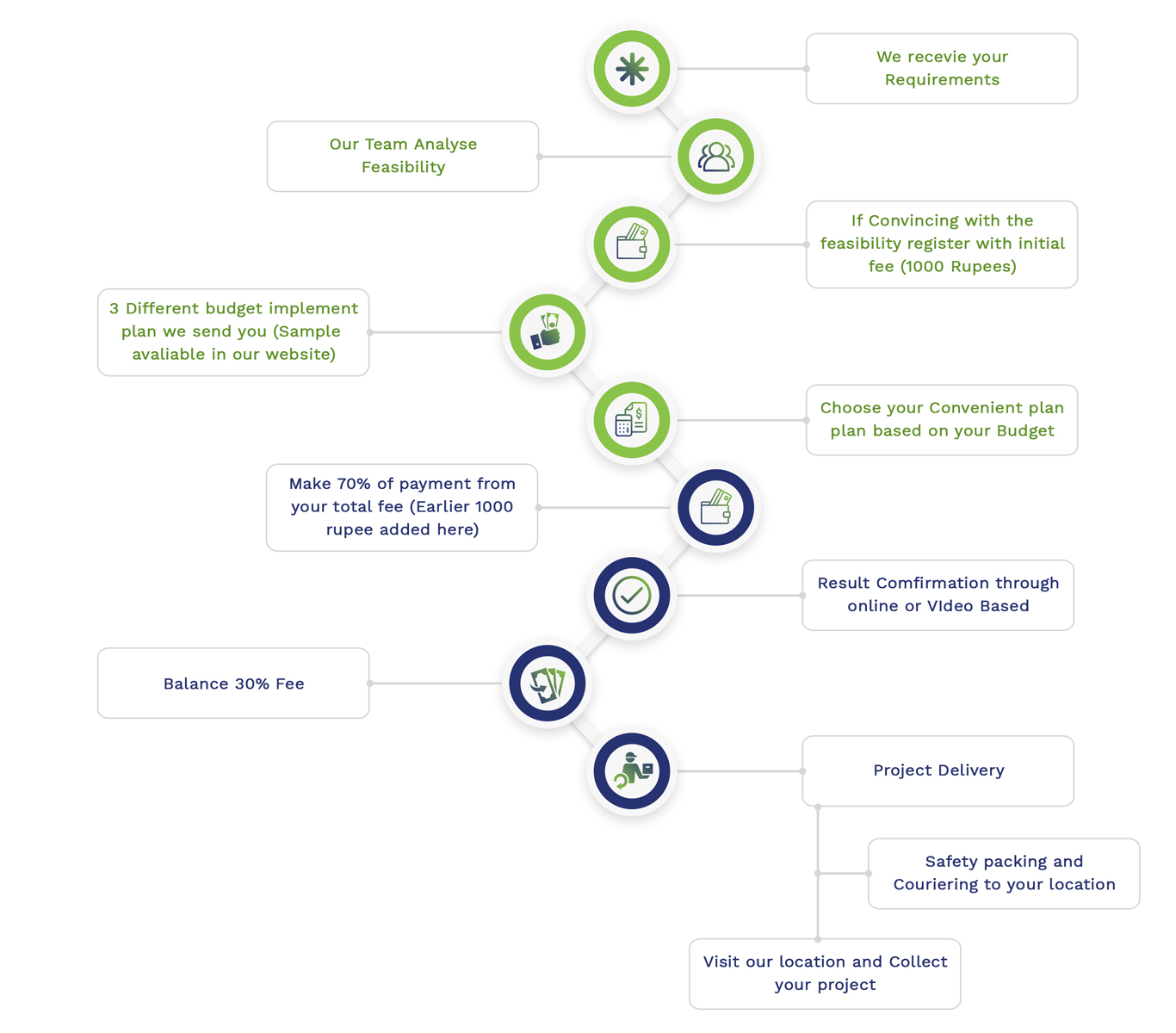
Simulation Projects Workflow
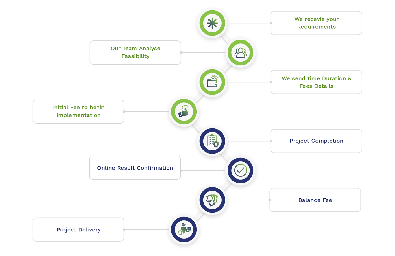
Embedded Projects Workflow